In this section, we present WPs’ objectives and the results that CuBER consortium has achieved until now.
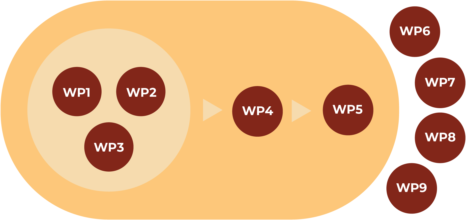
Below, we present a scheme of the WPs of the project. This scheme is not fixed, WP4 and WP5 have started their work before the previous ones finish. All technological WPs are interconnected with each other.
WP1 System specification
The objective of this WP is to write detailed specifications for a 90-cell 5 kWAC CuRFB power system to be integrated in a pilot plant equipped with PV/T solar panels and validate its performance for Smart Grid and residential self-consumption applications.
Task 1.1 - Specification of cell components, selection of materials, and experimental set-ups: the components of the CuRFB cell were identified and listed and a list of commercial products (for electrodes and separator) was selected as the benchmark, as well as the electrolyte composition. The main characterization techniques have been identified for each component of the cell. The physical-chemical characterization of electrolyte in terms of conductivity, viscosity, density, as well as the evaluation of solubility and stability, has provided information for the optimization of the electrolyte to be used in the CuRFB. To allow a feasible comparison between the partners, the components to be used in a lab-scale RFB unit were also identified.
Task 1.2 – Specifications for short stacks and full-size 5kW stack prototypes: the technical specifications for the stacks and short stacks to be produced in WP3 and incorporated in the CUBER prototype were identified. The cell development in WP3 is oriented to obtain a low-cost and high-performance stack suitable for mass production. Additionally, the lab-scale cell and short stack specifications to be used in WP2 were named.
Task 1.3 - Definition of hydraulic circuits and sensor networks: the thermal management system (TMS) layouts are being evaluated regarding cost, availability, and drawbacks. The relevant battery parameters to be considered for the tank and pump specification are summarized and the first estimation of the maximum flow was obtained. Additionally, the pressure drop was calculated for different flow rates and the tank size was estimated.
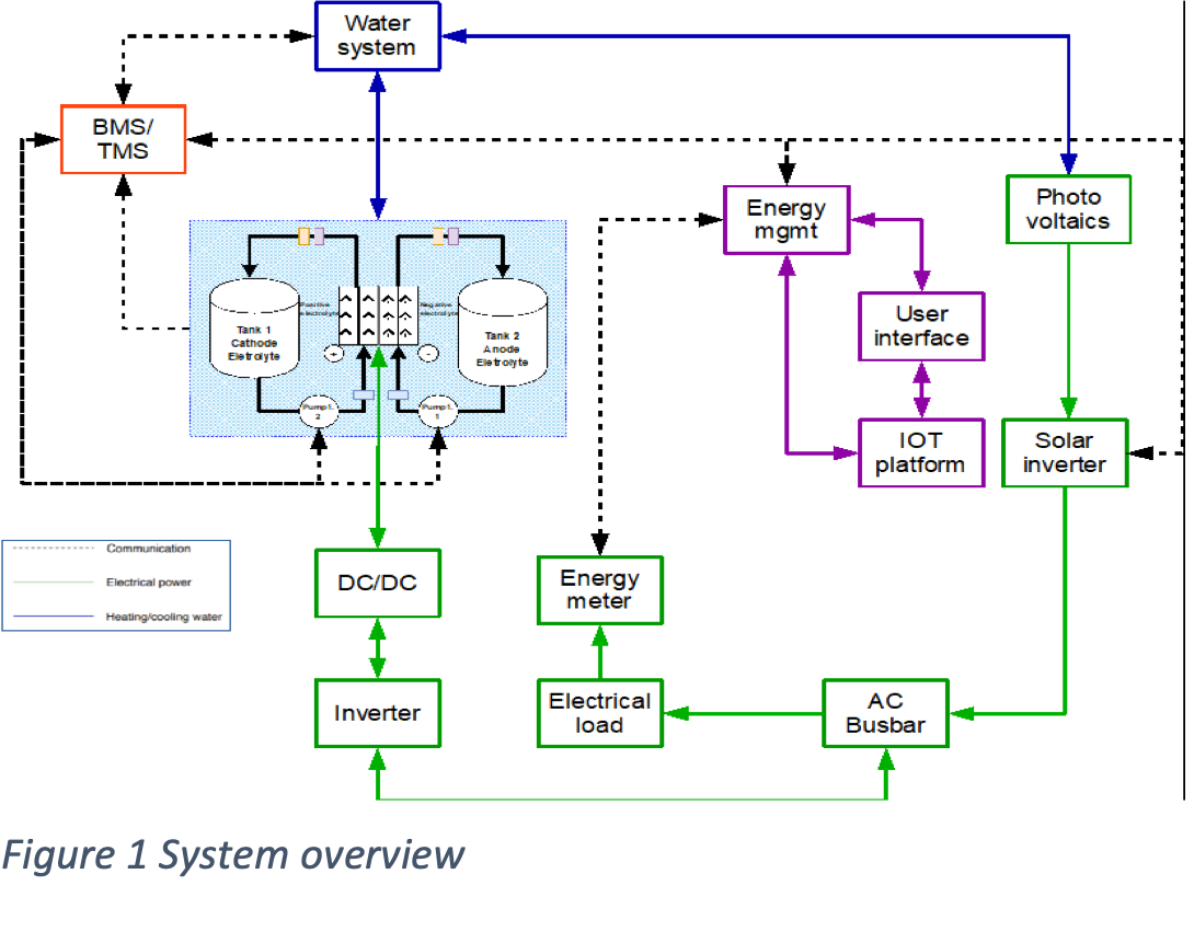
Task 1.4 - Specifications for the power electronics: the power system overview was made considering the battery management system (BMS) and system interfaces were identified. The functional decomposition of the CUBER electrical system was made and the subordinate functions were described. The main policies and regulations were identified. The BMS controls the charging and discharging. The BMS will control the pumps and valves in the hydraulic system, as well as handle the TMS and communicate with the power electronics and the sensors for the BMS/TMS. The BMS is in turn governed by the instructions provided by the IoT platform, which also considers external information such as power generation and consumption profiles, meteorological predictions, and energy pricing to decide whether to charge the battery, discharge the battery, or res
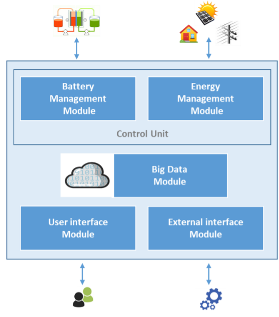
Task 1.5 - This task includes the adaptation of the backend of the NVision’s datASSIST platform. DatASSIST will be adapted to support the overall system control and management, data handling and communication with the outside world to deliver the required distribution system services. Therefore, user friendly interfaces will be developed by NVISION, considering customer requirements, to enable the interaction between the users, the system and the grid. Furthermore, the IoT platform allows the interoperability of the system with third parties. The solution will provide an industry standard Restful API for interoperability with 3rd party solutions/ services, affording the possibility of supplying specific services like, for example, energy trading services for shared self-consumption in industries and households.
The datASSIST software platform has been structured into different integrated modules, which can be observed in the figure. Some already exists and need to be adapted, while others will be developed from scratch.
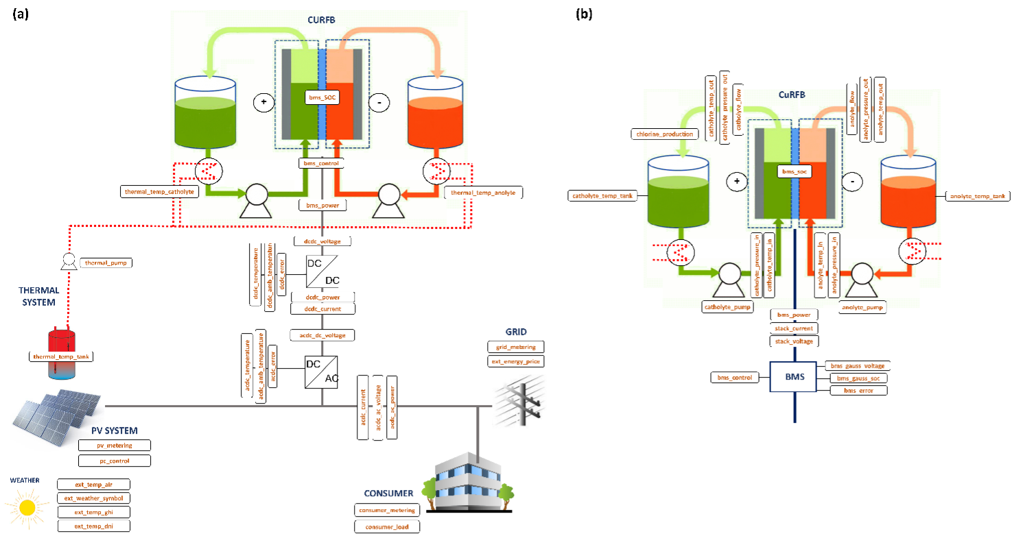
Data exchange between modules required sensors and actuators. The definition of required sensors and actuators, their specifications and placement in the system have been elaborated according to an optimal control of the whole system and a clear visualization for the user, as can see in the next figure.
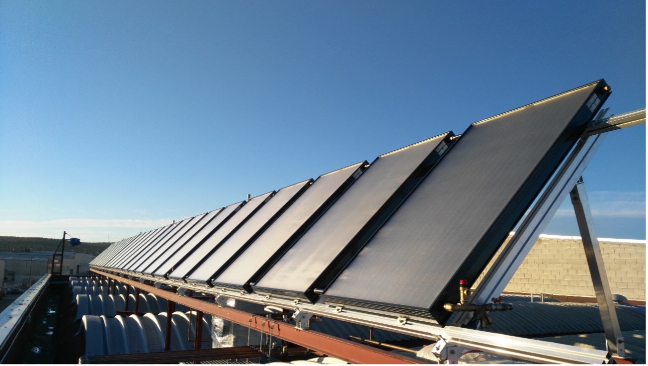
Task 1.6 - This task includes thedefinition of the current pilot plant, where the CuBER prototype will be installed. In an internal report, ENDEF presents an in-depth description of the components, equipment, and monitoring devices currently present in ENDEF facilities, where the CUBER prototype will be integrated once finished.
The current is composed by several hydraulic circuits. To this purpose, only the solar circuit is expected to be used, composed of 25 PV/T units (265W each) to provide electricity for the battery and heat to two storage tanks through the internal heat exchanger.
WP2 Battery Components
This WP aims at optimizing the materials and the compositions of the core components of the CuRFB system: the electrodes, the electrolytes and the separators, to achieve an improvement of the DC efficiency of single cells and short stacks.
https://www.cuberproject.com/wp-admin/post.php?post=140&action=edit#Task 2.1 - Electroplating and stripping of copper: The objective of Task 2.1 is to study the electroplating and stripping of copper on carbon surfaces in chloride electrolytes using standard electrochemical methods as well as ex-situ characterization of the deposits by microscopy techniques Modification of electrode surface and the use of additives is also investigated. Cyclic voltammetry (CV) analysis in the proposed electrolyte at glassy carbon (GC) electrodes was performed to determine the potential for nucleation and layer growth, the removal potential and the efficiency of the overall process.
Task 2.2 - Positive half-cell: The objective of the Task 2.2 is to study the kinetics of the cuprous to cupric reversible reaction on different carbon surfaces by using standard electrochemical methods under different ionic concentrations, temperatures and flow conditions. Methods to modify the electrode surface are also taken into account. Two different types of commercial carbon felts were considered, one based on polyacrylonitrile and the other based on Rayon. Thermal treatments were performed followed by physicochemical analyses (thermogravimetric analysis in different conditions, Raman spectroscopy, resistivity tests) and voltammetric tests. https://doi.org/10.1016/j.jpowsour.2021.230846
Task 2.3 - Electrode design and manufacture: The use of bipolar plates as current collectors in the stacks, combined with 1) pre-treated carbon felts in the positive half-cell and 2) conductive coatings or inks to favour the nucleation of copper deposits in the negative half-cell, is addressed. This also allows to develop innovative and lower cost fabrication processes for the CuRFB stack, while enhancing performance. The most promising process found was the injection moulding of the frames and gaskets.
Both positive and negative commercial half-cell electrode materials were tested, and their use was investigated within the copper redox flow battery CuRFB. Modification of existing commercial electrodes demonstrated a 34% increase in voltage efficiency and 9% increase in current efficiency. Currently is under evaluation whether to proceed with a new process engineering or collaboration with suppliers to set-up large-scale production of modified electrodes.
Task 2.4 - Electrolyte optimization: The objective of Task 2.4 is to optimize the electrolyte composition for improved kinetics, high conductivity, and high solubility of the copper ions, low corrosion, low viscosity, stable deposition, and stripping of copper. Electrochemical performance, also in presence of additives, as well as rheological properties (e.g.: density, viscosity) are evaluated to optimize composition. Low cost sources for copper (CuCl2) and chloride (HCl, CaCl2 or mixtures) have been identified. A final set of nine solutions has been selected and deeply characterized. https://doi.org/10.3390/batteries7040083
Task 2.5 - Use of Leacheate as Electrolyte: In the Task 2.5 the purification of atacamite leachates is studied to achieve an electrolyte quality that can be used in copper redox flow batteries.
Acid mine drainage (AMD) is formed under natural conditions by oxidation of different minerals, where it leaches the rocks and releases toxic metals to the environment making AMD an undesirable side effect of mining. On one end, the goal of the task is to use AMD as a raw material for the production of copper electrolyte solutions. On the other hand, the project also aims at the environmental sustainability of the entire copper redox flow battery and thus also of the copper mining. For this reason, the focus of this work is also on copper mines in very remote regions where, despite commercially available technology, significant environmental damage occurs because appropriate AMD treatment is not carried out. Copper has the highest toxicity of the metals included in the CUBER model AMD. Furthermore, copper is a relatively valuable non-ferrous metal and for this reason can still be economically recovered even with increased extraction efforts.
A method for very remote areas will be investigated as an alternative to active treatment methods, which can be used primarily at active copper mines with high infrastructure standards: passive electroless metal deposition.
Task 2.6 - Separator optimization: For the CuRFB to be a competitive alternative to vanadium redox flow batteries (VRFB) and iron chromium redox flow batteries, the cost of the CuRFB system must be kept low. For this reason, the CuRFB can’t employ the current commercial ion selective membrane options. Ex-situ characterization of separators often does not provide clear correlation with in-situ characterization for this reason shortly after the kickoff of the CUBER project the design process was initiated for the CuRFB unit to allow for separator screening and testing. Version 1 and 2 of the CuRFB unit have been designed and manufactured. Several types of membranes have been tested as separators; namely porous membranes, proton exchange membranes, anion/cation exchange membranes have been tested to assess their performance in terms of current and voltage efficiency and understand how they affect the self-discharge and battery capacity decay.
Task 2.7 - Single cell and short stack manufacture and testing: The objective of Task 2.7 is the characterization of a cell with the most promising electrolyte, separator and electrode structures from the previous Tasks. A final revision of the CuRFB (V3 CuRFB unit) has been manufactured. Tests on the CuRFB unit have been carried out at 60°C by galvanostatic charge/discharge cycles ad different current densities, with different separators and with materials that has been subjected to different treatments.
WP3: Stack development
The objective of WP3, Stack development, is to develop the critical components to achieve the performance and cost objectives of the project. The outcome of this work package will be two 5 kWDC stacks, coupled with the BMS and the power electronics, and ready for integration, and for the test and validation work packages.
Task 3.1 - Negative half-cell design and modelling:
The stack was designed considering the electrodeposition of copper on the negative electrode surface. CFD simulations to assess the flow path and velocity distribution inside the cell at different copper accumulation levels at the negative electrode. Several versions of a lab size RFB cell were designed and developed for preliminary components and electrolyte testing in WP2.
Task 3.2 - Flow frames and gaskets: Design and manufacture specifications: the main activities concerned the design of flow frames around negative electrode materials and exploration of production methods.
Task 3.3 - Stack manufacture & assembly: fine tuning of the stack prototype design according to the experiences from the negative half-cell modelling, prototype testing, design and manufacture specifications of flow frames and gaskets are made.
Task 3.4 - System preliminary testing: This task has not started.
Task 3.5 - The power electronics tasks are twofold in this project:
- Test the charging and discharging of the battery (this relates to the main objective of the project) under realistic conditions. The full stack requires 5kW of power at the DC interface.
- Convert the electrical energy such that the energy to and from the battery can used as a storage system for energy to and from the power grid at 400 V RMS phase-to-phase voltage.
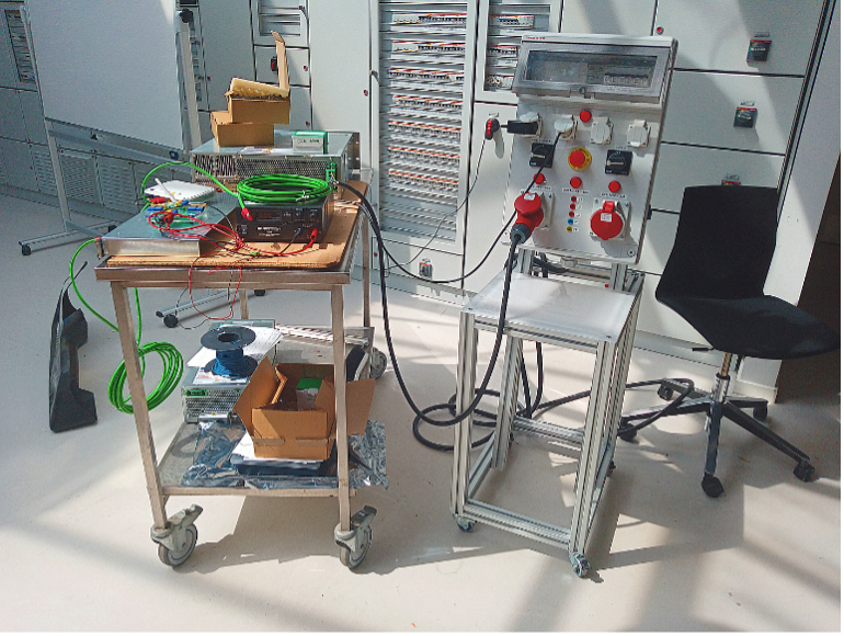
The main components for the final power electronic subsystem are the bidirectional DC/DC converter and the grid connected bidirectional inverter. Due to long lead times currently experienced in power electronics purchasing, an inverter and connected charger that fulfill the final system requirements, and comply with relevant standards, have already been purchased. The choice is an EU-sourced inverter/charger system. The inverter is a Trumpf AC 3025 inverter and the DC/DC converter is a Trumpf Truconvert DC 1008 converter.
The MODBUS TCP connection is going to be running in a Raspberry Pi 4, but development start on a PC first. To facilitate this, a MODBUS TCP client is written in Python that can communicate with the MODBUS TCP server in the inverter and the charger. Since the client will be part of the BMS server, the software is designed and developed in unison.
Task 3.6
- The BMS must communicate with the solar inverter and energy management system (EMS) to dictate inverter charge/discharge behaviour in response to available power and consumer demand.
- The BMS must communicate with the cathode and anode electrolyte pumps to ensure an appropriate amount of electrolyte flow through the stack while maintaining safe operating pressures in the battery’s hydraulic system.
- The BMS – in a subfunctionality typically referred to as its Thermal Management System (TMS) – must control the associated water system to ensure a proper level of forced cooling or heating of the system. This is particularly important as, pursuant to Task 2.4 and unlike well-known existing RFB technologies such as the VRFB, optimal stack operating temperature is expected to be well above ambient.
In the MVP stage of BMS development, which is the current stage of BMS development, the individual functionalities are considered as stand-alone, single-input/single-output (SISO) problems to the extent that this is practically and safely feasible. This implies the design of separate charge, flow, and temperature controllers based on robust, rigorously proven industry principles such as the PID regulator, and the design of state-of-health estimation primarily concerned with detecting major battery degradation. It also implies TMS design with an initial focus on keeping the system within a safe temperature range, rather than a narrower optimal temperature range.
WP4: System Integration
WP4 envisages the design of the hydraulic system, sensors, and automation as well as the integration of all the system components into a transportable 5 kW power system. This WP will define the strategy for system integration, to be used at a later stage for test and validation.
The WP is divided into 5 tasks.
Task 4.1 - Hydraulic system configuration: the current VisBlue system, based on vanadium electrolyte, is being analyzed to identify the elements that will need to be adapted to the CUBER electrolyte and WP1 specification. The main activities of the T4.1 include the acquisition of corrosion-resistant pumps, valves, piping, and electrolyte tanks according to the specifications from WP1. This task foresees the design of the hydraulic system, to minimize pumping losses and improve the BoP, and the integration of the TMS. Visblue is carrying out an internal survey of the system's equipment and peripherals. This review aims at identifying the critical elements that may need to be adapted to the system under development in the CUBER project, in particular concerning copper electrolyte, i.e., electrolyte storage tanks, pumps, sensors, and tubing as defined in T1.3. Special attention will be given to the OCV sensor cell for measuring the SoC of the electrolyte. Partner ITRB has also been exploring various options on heat exchangers, tanks, and pumps for the copper electrolyte within T1.3.
Task 4.2 - TBD
Task 4.3 - Control strategies and sensor networks: this task details the two-reference controllers (current reference controller and flow reference controller), as well as the state-of-health (SoH) estimator. The reference controllers consist of a current reference controller, which identifies an appropriate output current reference to the charger based on a reference from the EMS, and a flow reference controller, which identifies an appropriate flow rate reference for the variable-speed electrolyte pumps. The SoH estimator is based on a coarse-grained first-order equivalent circuit approach and the Current Interruption (CI) technique.
Task 4.4 - Adaptation of the nAssitsTM IoT platform to the new application: As the datASSIST software platform will be reused from one that is currently in commercial use, part of the needed functions may totally or partially exist already. In consequence, the adaptation of the existing features of the software platform and the implementation of the new functionalities take place in this task. In addition, an open API will be implemented to allow the interoperability of the platform with third parties. Moreover, communication protocols are defined. NVision team has already launched an initial demo of the IoT platform that made posible te get feedback for all implemented sensors provided by Aarhus. Moreover, some appis have been proposed to obtain weather information and electricity prices (https://www.esios.ree.es/es/pagina/api, https://solarwebservices.ch/) and they have been already integrated in the platform. A consumer profile has been defined based on a calculus combination of daily profiles and yearly profiles.
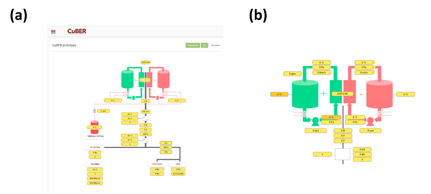
Task 4.5 - Development of the front-end application: user interface: A web based graphical user interface will be developed in this task. This GUI will allow an operator/user to interface with the system (CuRFB + Solar panels) and visualize data gathered by the sensor network and/or processed data from the AI components (Task 4.5 outcomes) running in the backend. The definition of the graphical user interface will be supported by end-user requirements provided by ENDEF.
The mock-up of the Graphical User Interfaced of the datASSIST IoT platform has been setted up of the components of the Azure architecture required for the CUBER project. As represented in the figures, user interface has been designed in a two levels composition: first level (figure a) allows the complete CuBER system sensor data to be visualised; and second level (figure b), which can be access by a simple click, focused on flow cell and BMS specific variables.
WP 5: Testing and validation in a pilot application
This WP will lead with the integration of the battery in the particular application of ENDEF facilities, as well as the testing and validation of its operation during time.
Task 5.1 - CuRFB system modelling and BoP: The main activities of the T5.1 include the development of a battery system model of the CuRFB system. The development of T5.1 is linked to the outputs of WP1, WP3 and WP4. Preliminary work included a study using the vanadium case as a reference to understand the influence of the length of the flow channels on pressure drop and current losses by shunt-currents. Shunt current is a common phenomenon in all RFB stacks that incorporate parallel hydraulic flow and a common electrolyte manifold. Shunt currents are highly undesirable since they reduce current efficiency and may also lead to other problems such as gassing, corrosion and dendrite growth within channels that can restrict or block electrolyte flow.
WP 6: Life Cycle Assessment
The main aim of WP6 is to collect the Life Cycle Inventory information for the materials and processes used in the other WP and assess the environmental and economic performance.
A similar study was conducted by ITRB on the Life Cycle Cost Analysis.
Task 6.1 - Environmental, health & safety characterization of processes for application case studies: In month 6 a LCA Workshop took place in which the Data Collection Sheet (DCS) to be used for data collected was introduced to the partners and the whole collection process was explained. Furthermore, a first explanation and discussion about the target product system and the Functional Unit took place. Literature on LCA for Redox Flow Batteries (RFB) and Lithium-Ion Batteries (LiIB) has been reviewed by Fraunhofer to have a proper basis for comparison of the final LCA results. The hits of the survey were narrowed down to 26 publications of interest, which then were discussed with partners from the FLORES network and down-selected again. Furthermore, a legal framework review was done by Fraunhofer to ensure that the environmental impact of the materials and processes used is taken into account. The main focus lay on raw materials, production/placing on the market, Installation and disposal. Based on a first overview on the materials provided within the DCS, a hazard review on the materials was done. Basis for the review were material safety data sheets for each of the materials to outline a general hazard potential. Based on the Material information and the final application in the battery system, flow charts are prepared in which the processes with the highest impact are highlighted.
Task 6.2 - LCA/LCC to estimate environmental impacts: The environmental assessment follows the ISO 14040 series [ISO 14040:44] and the recommendations of the European Commission for Rechargeable Batteries [European Commission 2018]. Hence, first of all the goal & scope of the study was defined, followed by the data collection. This collection is done iteratively every 6 months. The product system is defined from cradle to grave/cradle and is the basis for all subsequent data collection. The impact assessment focuses in accordance with the Product Environmental Footprint Category Rules (PEFCR) for rechargeable batteries. Data collection started after goal and scope definition by spreading input/output tables to confirmed contact persons for each of the systems shown in the product system. The procedure will be iterative during the whole development process in order to improve the data quality continuously. Parallel to the data collection the system is modelled in GaBi Software, including different options for materials and components, as it is still under research and development.
In accordance with the LCA, ITRB is using the system boundaries, functional unit, goal and scope defined by FRAUNHOFER to perform the Life Cycle Cost Analysis (LCCA). Due to the novelty of the process, there is no methodological standard on how to perform a Life Cycle Costing Analysis. Therefore, ITRB carried out a review of the scientific literature which has been helpful to have a methodological reference and an overview of the LCCA of the competitive technologies. A preliminary LCCA was carried out considering raw estimations of costs by considering the cost data that the partners provided as an initial forecast. In order to have a market reference, research was performed also considering CUBER project’s competitors, the results will be considered as a starting point to compare the results of the LCCA. The lifecycle Assessment Management was planned. In particular, ITRB addressed the Integrated Lifecycle Assessment developing a parametric description of the process, which will allow to perform sensitivity analysis and optimization.
Task 6.3 - Framework and policy recommendation: The main objective of this task is to analyse the legislative obstacles and issues at national and/or European levels, which may impede to implement CUBER’s technologies/products. At the end of this task, it will be present a policy brief.